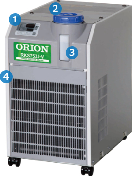
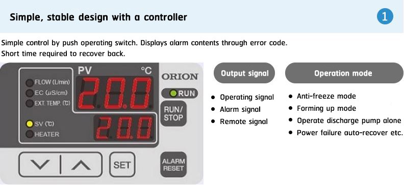
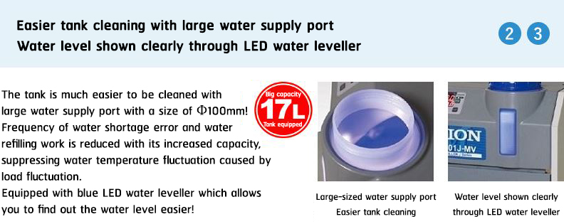
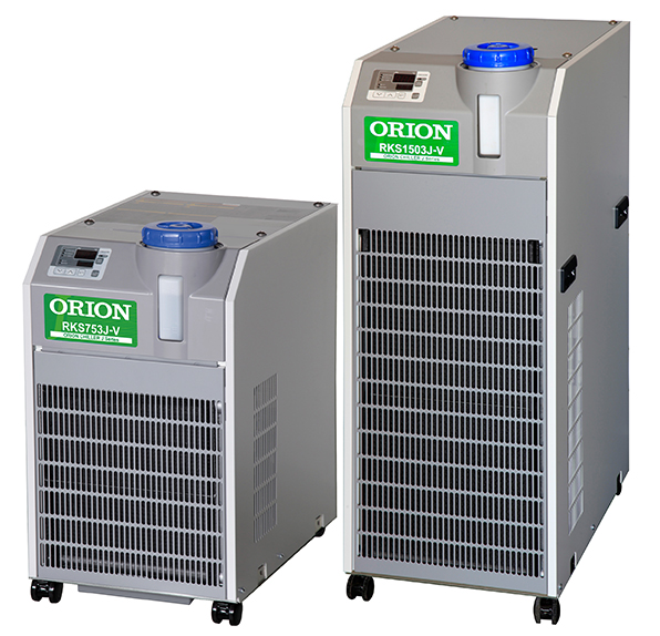
RKS753J-V-00000/ RKS1503J-V-00000
|
Cooling capacity |
: |
1.1 kW (RKS753J-V-00000) 2.4 kW (RKS1503J-V-00000) |
|
Operating Ambient Temp. Range |
: |
10~40℃ |
|
Operating Liquid Temp. Range |
: |
15~35℃ |
|
Control Precision |
: |
±2.0℃ |
Features
Made even easier to use!
Common for all RKS J series models
|
|
||||
|
|
|||||
|
|
|||||
 |
|||||
Accessories
Many functional specifications available to match your application
The list of accessories is available on a different page. Please click the link below to take a look.
Specifications
| Model | RKS753J-V-00000 | RKS1503J-V-00000 | |||
| Performance | Compressor output (50Hz) | HP | 1.1 | 2.4 | |
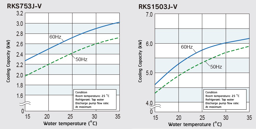
| Cooling capacity (50Hz)*1 | KW | 1.8 | 4.1 | ||
| TR | 0.5 | 1.2 | |||
| BTU/h | 6,100 | 13,900 | |||
| Ambient Temp. Range | ℃ | 10~40 | |||
| Operating temperature range (Liquid temperature) | ℃ | 15~35 | |||
| Operating Water Pressure | Mpa | 0.05~0.2/0.3(50/60Hz) | 0.1~0.5 | ||
| Control accuracy*4 | ℃ | ±2.0 | |||
| Min. Operating circulation rate (50/60Hz) | L/min | 10 (Head 20/30m) | 12/21 (Head 50m) | ||
| Power specification | Power source*2 | V(Hz) | Three-phase 200±10%(50/60)・220±10%(60) | ||
| Power consumption (50/60Hz)*1 | kW | 0.9/1.1, 1.1 | 1.8/2.2, 2.2 | ||
| Electric current (50/60Hz)*1 | A | 4.1/4.1, 4.1 | 6.8/7.4, 7.4 | ||
| Power capacity*3 | kVA | 2.0 | 4.2 | ||
| Breaker capacity*5 | A | 10 | 15 | ||
| Operation control method | Compressor ON/OFF Control | ||||
| Equipment detail | Refrigerating compressor | Structure | Fully sealed rotary type | ||
| Output | kW | 0.85 | 1.8 | ||
| Condenser | Corrugated fin & Parallel flow tube type | ||||
| Heat exchanger | Structure | Plate type heat exchanger | |||
| Material | SUS316 (Brazing: Cu) | ||||
| Discharge pump | Structure | Cascade type | |||
| Output | kW | 0.25 | 0.4 | ||
| Water tank capacity | L/min | Approx. 17 | |||
| Refrigerant | R-410A | ||||
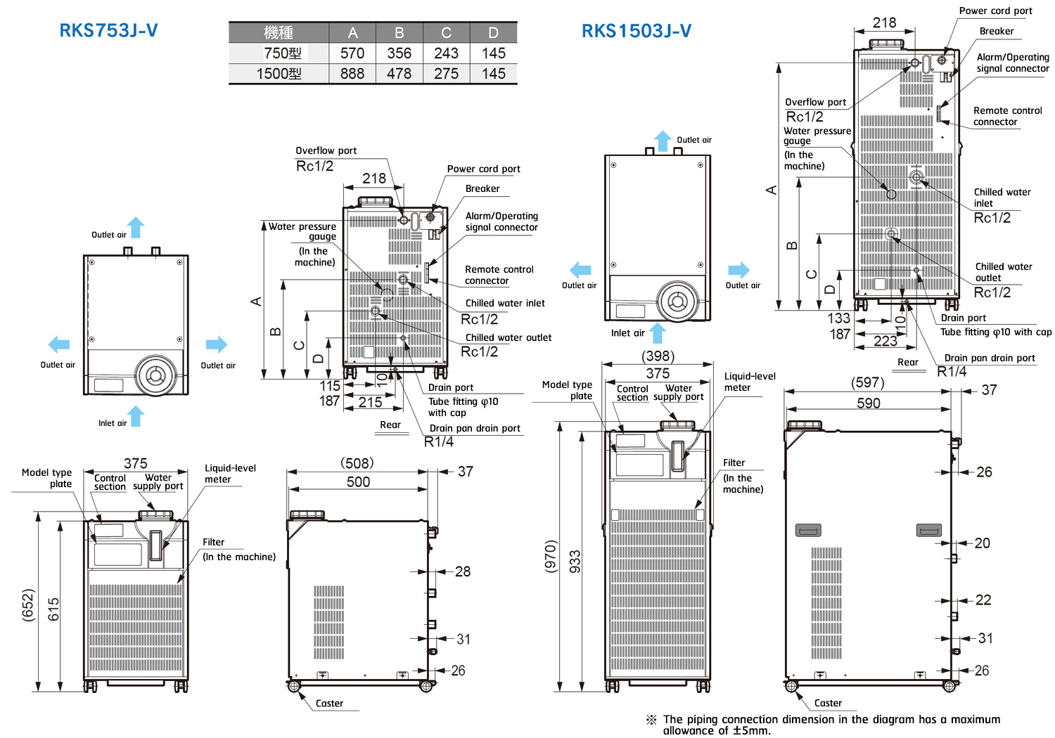
| External dimensions (Height x Length x Width) | mm | 615×500×375 | 933×590×375 | ||
| Product mass (Dry weight) | kg | 45 | 67 | ||
| Operation noise level (50/60Hz)*6 | dB | 61/63 | 63/66 | ||
| *1 Under the following conditions: Chilled water temp.: 20 °C, Ambient temp.: 32 °C, Max. discharge pump circulating load. Cooling capacity is at least 95 % of listed figures. Heating capacity will change according to operating conditions. | |||||
| *2 Source voltage phase unbalance should be less than ±3 %. | |||||
| *3 The figure noted is when the equipment is operating at the highest capacity of its normal operating range. | |||||
| *4 When the current load is continuously within ±10 %, and the ambient temperature is stable. However does not include starting times or when the heat-load exceeds the chiller capacity. |
|||||
| *5 Comes standard with a built-in overload protection circuit breaker (NFB). | |||||
| *6 Operating noise levels are from a position of 1 m in front of the product and at a height of 1 m. | |||||
| Note 1) Liquid (chilled water) that can be used are either clean water and a 30 to 40 % ethylene glycol solution. Note that there will be a drop in cooling capacity of 10 % if using a 30 to 40 % ethylene glycol solution. Alternatively, if deionized water is to be used, it should have an electrical conductivity of at least 1 μs/cm. |
|||||
| Note 2) Heat output from the unit (in kW) is approx. 1.3 times that of the cooling capacity. | |||||
| Note 3) Depending on the operating environment, condensation may form on piping inside the product, and temporary leakage of water from the pump mechanical seals may also occur, therefore a drain pan should be installed if required. | |||||
External Dimensions
Cooling Capacity
Pump characteristic curves


